In the last article on FlexRay we discussed on the protocol from the communication cycle perspective. In this article we will discuss about the frame format going into the details of what is there in a slot of a FlexRay frame.
As discussed in the last article, the Communication cycle is divided into Static Segment, Dynamic Segment, Symbol Window and Network Idle Time. Each Segment is further divided into Slots. ECU’s communicate over these slots. These slots contain the communication frame of FlexRay. Lets dive into the FlexRay Frames.
Each FlexRay frame can be divided into Header Segment, Payload Segment and Trailer Segment. The order of transmission of the frame on the bus is also the same i.e. first the header followed by payload and then the trailer.
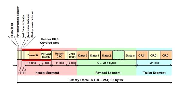
FlexRay Frame Format (Courtesy : Flexray Specification)
Header Segment :
The FlexRay header segment consists of 5 bytes. These bytes contain the reserved bit, the payload preamble indicator, the null frame indicator, the sync frame indicator, the startup frame indicator, the frame ID, the payload length, the header CRC, and the cycle count.
Reserved Bit : This bit is not used and should be ignored. The transmitting node should send it as ‘0’ and receiving node should ignore it.
Payload Preamble Indicator Bit : Depending on the segment in which this bit is transmitted as ‘1’, the part of the payload segment has to be interpreted differently.1. If this bit is ‘1’ in Static Segment, beginning of the payload is used as network management vector. NM vector in payload segment can vary from 0 to 12 bytes.
2. If this bit is ‘1’ in dynamic segment, beginning of the payload is used as message ID. Message ID in the payload segment can be of 2 bytes.
If this bit is ‘0’ then irrespective of the segment in which it is transmitted the payload does not contain a network management vector or a message ID.
Null Frame Indicator : The null frame indicator indicates whether or not the frame is a null frame, i.e. a frame that does contains any valid data in the payload segment.
If the null frame indicator is set to ‘1’ then the payload segment contains valid data.
Sync Frame Indicator : The sync frame indicator indicates whether or not the frame is a sync frame, i.e. a frame that is utilized for system wide synchronization of communication. Sync frames are only sent in the static segment.
If the sync frame indicator is set to ‘1’ then all receiving nodes shall utilize the frame for synchronization provided other conditions for synchronization are met.
Startup Frame Indicator : The startup frame indicator indicates whether or not a frame is a startup frame. Only coldstart nodes are allowed to transmit startup frames.
If the startup frame indicator is set to ‘1’ then the frame is a startup frame. A valid Startup frame is also a sync frame and should have the Sync bit also set to ‘1’.
Payload Length : These are 7 bits which indicate the size of the Payload segment. The value in the payload length corresponds to half the length of data in the payload segment i.e. if we want to transmit 100 bytes in the payload segment then the payload length will be 50. It can also be interpreted that each bit in the payload length represent a two byte word in the payload segment. The payload length shall be fixed and identical for all frames sent in the static segment of a communication cycle.
Header CRC : These are 11 bits which contains the CRC computed over the sync frame indicator, the startup frame indicator, the frame ID, and the payload length.
Cycle Count : These are 6 bits which indicate the transmitting node’s view of the value of the cycle counter at the time of frame transmission.
Payload Segment :
FlexRay Payload Segment can contain 0 to 254 bytes data. The number of bytes in the payload segment are always even as the payload length in the header segment represent a two byte word in the payload segment.
Depending on the value of the Payload Preamble indicator bit (in the header segment) and the segment(Static or Dynamic Segment) in which the frame is being transmitted the initial bytes in the payload segment can be interpreted as a Network Management Vector or a Message ID.
Trailer Segment :
These are 24 bits containing the CRC computed over the frame. This CRC is computed over all the field in the header and the payload segment. . These bits are are transmitted in the msb first format.
In the coming articles we will discuss about the Startup, Sync and the Wake-up procedures in FlexRay.